Welcome to the Titan 410 Paint Sprayer Manual. This guide provides essential information for setting up, operating, and maintaining your airless sprayer. Discover its features, troubleshooting tips, and optimal usage techniques to ensure professional results in painting projects.
1.1 Overview of the Titan 410 Paint Sprayer
The Titan 410 Paint Sprayer is a professional-grade airless spraying system designed for efficient and high-quality coating applications. It features advanced technology, including self-adjusting Quad Packings, ensuring consistent performance. Ideal for low- to medium-viscosity materials, it supports various coatings like latex, enamels, and stains. Built for reliability, the Titan 410 is part of the Impact Series, known for durability and precision. This manual guides users through setup, operation, and maintenance, helping to achieve professional results in painting projects. Its robust design and versatility make it a top choice for both professionals and DIY enthusiasts.
1.2 Importance of the Manual for Optimal Usage
This manual is crucial for maximizing the performance and longevity of your Titan 410 Paint Sprayer. It provides detailed instructions for setup, operation, and maintenance, ensuring safe and effective use. By following the guidelines, users can prevent common issues, optimize spraying techniques, and maintain the equipment’s reliability. The manual also covers troubleshooting, helping to resolve potential problems quickly. Proper adherence to the instructions enhances efficiency, reduces waste, and ensures professional-quality results. Refer to this guide regularly to get the most out of your Titan 410 and extend its lifespan.

Key Features of the Titan 410 Paint Sprayer
The Titan 410 features advanced airless spraying technology, offering high-pressure performance and versatility for various coatings. Its durable design ensures reliable operation and consistent results across projects.
2.1 Design and Build Quality
The Titan 410 is crafted with premium materials, ensuring durability and long-lasting performance. Its robust frame and high-quality components are designed to withstand rigorous use, making it ideal for professional applications. The compact and lightweight design enhances portability, allowing easy movement around job sites; Additionally, the sprayer features a user-friendly interface and ergonomic controls, providing comfort during extended use. Built with precision engineering, the Titan 410 delivers reliability and efficiency, making it a trusted tool for various painting and coating tasks. Its sturdy construction ensures minimal wear and tear, even under heavy-duty conditions.
2.2 Airless Spraying Technology
The Titan 410 employs advanced airless spraying technology, eliminating the need for compressed air. This method delivers paint under high pressure through a precision nozzle, creating a smooth, even finish with minimal overspray. The Impact Series fluid section and Self-Adjusting Quad Packings ensure consistent performance across various coatings, including stains, lacquers, and latex paints. This technology enhances efficiency, reduces material waste, and provides a professional-grade finish. Its design allows for quiet operation and portability, making it ideal for both small and large-scale projects. The airless system is known for its reliability and versatility in achieving high-quality results.
2.3 Versatility in Coating Applications
The Titan 410 excels in versatility, accommodating a wide range of coatings, including stains, lacquers, enamels, latex paints, and other low- to medium-viscosity materials. Its advanced design ensures consistent results across various surfaces, from smooth wood to rough textures. The sprayer’s adaptability makes it suitable for both small-scale projects, like furniture, and large-scale applications, such as exterior walls. The Impact Series fluid section and Self-Adjusting Quad Packings further enhance its ability to handle diverse materials efficiently, ensuring optimal coverage and minimal waste. This flexibility makes the Titan 410 a reliable choice for professionals and DIYers alike, delivering high-quality finishes across different coating types.

Setting Up the Titan 410 Paint Sprayer
Setting up the Titan 410 involves unboxing, initial inspection, and assembly. Place the siphon tube in mineral spirits and adjust the pressure to minimum. Ensure proper setup by following the provided instructions or setup videos for a smooth start.
3.1 Unboxing and Initial Inspection
When you unbox your Titan 410 Paint Sprayer, carefully inspect the contents to ensure all components are included and undamaged. Check for the sprayer unit, hoses, spray gun, tips, and additional accessories. Refer to the parts diagram in the manual to verify each item. Inspect the equipment for any signs of damage or wear. If any parts are missing or damaged, contact Titan customer support immediately. This step ensures proper setup and prevents operational issues later. Always follow the manual’s guidance for a smooth initial setup process.
3.2 Identifying Key Components and Parts
Familiarizing yourself with the Titan 410’s key components is crucial for effective operation. The main unit houses the motor and pump, while the spray gun and tip are essential for coating application. The hoses connect the pump to the gun, ensuring material flow. Additional parts like the siphon tube, return hose, and filter aid in smooth operation. Refer to the manual’s parts diagram to identify each component accurately. Understanding these elements will help you assemble, use, and maintain the sprayer efficiently, ensuring optimal performance in your painting projects.
3.3 Initial Setup and Assembly Instructions
Begin by unboxing and inspecting the Titan 410 for any damage. Attach the spray gun to the main unit and connect the hoses securely. Place the siphon tube in a container of mineral spirits and position the return hose in a waste container. Set the pressure to the minimum and prime the system by turning the pump on briefly. Ensure all connections are tight to prevent leaks. Follow the manual’s assembly diagram for correct configuration. Proper setup ensures smooth operation and prevents potential issues during use.
Operating the Titan 410 Paint Sprayer
Master the Titan 410 by understanding the control panel, adjusting pressure settings, and employing proper spraying techniques for various surfaces. Always follow safety guidelines and use protective gear.
4.1 Understanding the Control Panel
The Titan 410’s control panel is designed for intuitive operation. It features a pressure gauge, flow control knob, and power switch; The pressure gauge displays the current PSI, while the flow control allows you to adjust the paint output. Locate the emergency stop button for quick shutdown. Familiarize yourself with the panel’s layout to ensure smooth operation. Always refer to the manual for specific instructions on adjusting settings. Proper control panel usage ensures efficient painting and minimizes waste. Learn each function to maximize your sprayer’s performance and safety.
4;2 Adjusting Pressure and Flow Settings
Adjusting the Titan 410’s pressure and flow settings ensures optimal painting results. Start by setting the pressure to the minimum recommended for your coating material. Use the flow control knob to regulate the paint output, increasing or decreasing as needed. Always prime the system before adjusting settings to ensure proper flow. For thicker materials, higher pressure may be required, while thinner coatings benefit from lower settings. Monitor the spray pattern and adjust accordingly to achieve a smooth, even finish. Proper adjustment prevents overspray and material waste, enhancing efficiency and final results.
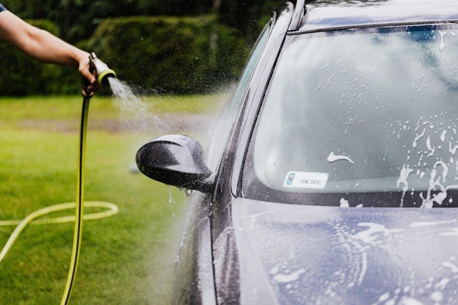
4.3 Spraying Techniques for Different Surfaces
Mastering spraying techniques for various surfaces ensures professional results with the Titan 410. For smooth surfaces like wood or metal, maintain a consistent 12-inch distance and use steady, horizontal strokes. On uneven or textured surfaces, such as drywall or concrete, adjust your technique to shorter, controlled passes. Always keep the sprayer nozzle perpendicular to the surface to avoid uneven coverage. For large areas, overlap your strokes slightly to maintain consistency. Adjust pressure and flow settings based on the surface type to prevent overspray and ensure an even coat. Practice on a test surface before applying paint to achieve the desired finish.
Safety Precautions and Best Practices
Always wear protective gear, including gloves and goggles, when operating the Titan 410. Ensure good ventilation and avoid flammable materials. Keep loose clothing tied back and avoid overreaching. Never touch electrical components with wet hands. Regularly inspect hoses and connections for damage. Follow all safety guidelines in the manual to prevent accidents and ensure optimal performance.
5.1 General Safety Guidelines
Always prioritize safety when using the Titan 410 Paint Sprayer. Wear protective gear, including gloves and goggles, to prevent injury. Ensure the workspace is well-ventilated and free from flammable materials. Avoid wearing loose clothing that could get caught in the equipment. Keep children and pets away from the work area. Never touch electrical components with wet hands or operate the sprayer in wet conditions. Regularly inspect hoses and connections for damage. Follow all safety precautions outlined in the manual to minimize risks and ensure safe, efficient operation.
5.2 Proper Use of Protective Gear
Always use protective gear when operating the Titan 410 Paint Sprayer to ensure safety. Wear a mask or respirator to avoid inhaling paint fumes. Safety goggles protect your eyes from splatters. Use gloves to prevent skin irritation and maintain a firm grip on the equipment. A hat or overalls can shield clothing from paint residue. Steel-toe boots are recommended for workplace safety. Ensure all gear fits properly and is in good condition. Regularly inspect your protective equipment for damage or wear. Refer to the safety section of the manual for detailed guidelines on selecting and maintaining the right protective gear for optimal protection.
5.3 Avoiding Common Mistakes During Operation
To ensure optimal performance and safety, avoid common mistakes when using the Titan 410 Paint Sprayer. Never operate the sprayer without proper setup, as this can lead to inconsistent results. Always prime the system before spraying and avoid using excessive pressure, which may cause overspray. Keep the nozzle clean and avoid clogs by straining paint. Do not spray in direct sunlight or high winds, as this can affect finish quality. Regularly inspect hoses and connections for leaks. Never leave the sprayer unattended while in use. Following these guidelines will help prevent accidents and ensure professional-grade results.
Maintenance and Cleaning of the Titan 410
Regular maintenance is crucial for the Titan 410 Paint Sprayer’s longevity. Clean the pump, hose, and nozzle after each use to prevent paint buildup. Flush with solvent and lubricate moving parts to ensure smooth operation. Store the sprayer in a dry, cool place to avoid rust and damage; Follow the manual’s cleaning and lubrication schedules for optimal performance and reliability.
6.1 Daily Cleaning Routine
A daily cleaning routine is essential to maintain the Titan 410 Paint Sprayer’s performance. Start by flushing the system with mineral spirits to remove paint residue. Clean the pump, hose, and nozzle thoroughly, ensuring no paint dries on the components. Use a soft brush to wipe down the exterior and remove any splatters. Regularly inspect and replace worn-out seals or O-rings to prevent leaks. Store the sprayer in a dry, cool place after cleaning. Proper daily maintenance ensures optimal functionality and extends the lifespan of your Titan 410 Paint Sprayer.
6.2 Storage and Long-Term Maintenance Tips
To ensure the longevity of your Titan 410 Paint Sprayer, proper storage is crucial. After cleaning, store the sprayer in a dry, cool place away from direct sunlight and moisture. Regularly inspect hoses and connections for signs of wear or damage. Lubricate moving parts periodically to maintain smooth operation. Keep the sprayer and its accessories in the original packaging or a protective case when not in use. For extended periods of inactivity, drain all fluids and follow the manual’s specific storage instructions. This will prevent corrosion and ensure the sprayer remains ready for future use.
6.3 Lubrication and Parts Replacement
Regular lubrication is essential for maintaining the Titan 410 Paint Sprayer’s performance. Apply lubricant to moving parts, such as the pump and valve components, as specified in the manual. Replace worn or damaged parts promptly to prevent further damage. Use only genuine Titan replacement parts to ensure compatibility and maintain warranty coverage. Hose, seals, and packings are common parts that may require replacement over time. Refer to the manual for a detailed parts diagram and instructions for replacement procedures. Proper maintenance ensures optimal functionality and extends the lifespan of your sprayer.
Troubleshooting Common Issues
Troubleshoot Titan 410 Paint Sprayer issues by identifying symptoms, checking for clogs, and ensuring proper setup. Refer to the manual for detailed solutions and maintenance tips.
7.1 Identifying and Resolving Clogs
Clogs in the Titan 410 Paint Sprayer can disrupt painting projects. To resolve this, turn off the unit and clean the nozzle and filter with mineral spirits. Soak parts if necessary. Use a soft brush to remove dried paint; Regular maintenance prevents clogs, ensuring smooth operation. Always refer to the manual for detailed cleaning procedures to maintain performance and extend the sprayer’s lifespan.
7.2 Addressing Pressure Fluctuations
Pressure fluctuations in the Titan 410 Paint Sprayer can affect painting consistency. To address this, check for blockages in the hose or nozzle and ensure the filter is clean. Adjust the pressure control knob to stabilize output. If issues persist, refer to the manual for guidance on resetting or recalibrating the system. Proper setup and regular maintenance, such as cleaning the fluid section, can prevent pressure variations. Always follow the manufacturer’s recommendations to maintain optimal performance and achieve smooth, even coats in your projects.
7.3 Solving Electrical or Mechanical Failures
If your Titan 410 Paint Sprayer experiences electrical or mechanical issues, start by checking the power supply and ensuring all connections are secure. Reset the circuit breaker or replace blown fuses if necessary. Inspect for worn or damaged parts, such as the motor or gear assembly, and replace them using genuine Titan parts. Consult the manual for troubleshooting guides or contact Titan’s customer support for assistance. Regular maintenance, like lubricating moving parts and cleaning the unit, can prevent such failures. Always follow safety guidelines when handling electrical components to avoid further damage or injury.

Technical Specifications of the Titan 410
The Titan 410 operates at a maximum pressure and flow rate, suitable for low to medium-viscosity coatings, ensuring efficient and professional painting results across various surfaces.
8.1 Maximum Pressure and Flow Rate
The Titan 410 showcases impressive performance with a maximum pressure of up to 3000 PSI and a flow rate of 0.47 GPM. These specifications ensure efficient application of various coatings, from thin stains to medium-viscosity paints. The high pressure allows for smooth, consistent coverage, while the flow rate accommodates larger projects without compromising quality. This combination makes the Titan 410 ideal for both professional contractors and DIY enthusiasts, delivering reliable results across different painting tasks and surfaces.
8.2 Compatible Coatings and Materials
The Titan 410 is designed to handle a wide range of coatings, including stains, lacquers, enamels, and latex paints. It efficiently sprays low- to medium-viscosity materials, making it suitable for various painting projects. The sprayer is compatible with water-based and solvent-based coatings, ensuring versatility for both interior and exterior applications. Always use recommended materials to maintain optimal performance and avoid clogging. Proper setup and priming are essential for consistent results with different coating types. Refer to the manual for specific guidelines on material compatibility and preparation.
8.3 Dimensions and Weight
The Titan 410 Paint Sprayer is designed to be compact and portable, with approximate dimensions of 20 inches in height, 15 inches in width, and 30 inches in length. It weighs around 60 pounds, making it easy to transport and maneuver during painting tasks. These specifications ensure the sprayer is both durable and lightweight, providing convenience for professionals and DIY enthusiasts alike. The compact design allows for efficient storage and easy handling, ensuring optimal performance across various projects. Always refer to the manual for precise measurements and weight specifications.
Repair and Replacement Parts
For the Titan 410, genuine parts ensure optimal performance. Refer to the manual for a detailed parts diagram and instructions on replacing components. Contact Titan support for assistance.
9.1 Identifying Genuine Titan Parts
Identifying genuine Titan parts is crucial for maintaining your sprayer’s performance. Look for the Titan logo and part numbers matching your manual. Genuine parts ensure compatibility and reliability. Always purchase from authorized dealers to avoid counterfeit products. Visit the Titan website for a list of approved distributors. Using genuine parts guarantees safety and optimal functionality, adhering to Titan’s quality standards. For any doubts, contact Titan’s customer service for verification.
9.2 Installing Replacement Components
Installing replacement components on your Titan 410 requires careful attention to detail. Always use genuine Titan parts to ensure compatibility and performance. Start by disconnecting power and allowing the sprayer to cool. Clean the area around the component to prevent contamination. Remove the faulty part using appropriate tools, following the manual’s guidance; Install the new component securely, tightening fasteners as specified. Test the sprayer to ensure proper function. Refer to the manual for specific instructions, as procedures may vary by part. Always follow safety precautions to avoid injury or damage.
9.3 Warranty and Repair Services
The Titan 410 Paint Sprayer is backed by a comprehensive warranty program, ensuring coverage for defective parts and workmanship. For warranty claims, contact Titan’s customer service or visit an authorized service center. Repairs must be performed by certified technicians to maintain warranty validity. Self-repair attempts may void the warranty. Titan also offers extended support through dedicated repair services, providing genuine parts and expert assistance. For inquiries, call Titan’s customer service at 1-800-526 or visit their official website for detailed warranty terms and repair options.
Frequently Asked Questions
This section addresses common user queries about the Titan 410 Paint Sprayer, such as initial setup, troubleshooting, and maintenance. Find solutions to frequently encountered issues here.
10.1 Common User Queries
Users often ask about setup steps, troubleshooting clogs, and adjusting pressure. They inquire about compatible coatings and maintenance routines. Frequently, questions arise about resolving pressure fluctuations and understanding error codes. Many seek tips for extending the sprayer’s lifespan and improving paint flow consistency. Others ask about warranty details and locating authorized service centers. Additionally, users want to know how to properly store the sprayer and identify genuine Titan parts. These queries are addressed to ensure optimal performance and longevity of the Titan 410 Paint Sprayer.
10.2 Solutions to Frequently Encountered Problems
For clogs, clean the spray tip and filter regularly. Pressure fluctuations can be resolved by adjusting settings or checking for blockages. Electrical issues may require resetting the unit or consulting the manual. If parts wear out, replace them with genuine Titan components. Always refer to the troubleshooting guide for specific solutions. Persistent problems? Contact Titan’s customer service or authorized dealers for professional assistance. Proper maintenance and adherence to guidelines can prevent many issues, ensuring smooth operation and extending the sprayer’s lifespan.
10.3 Tips for Extending the Lifespan of the Sprayer
To extend the lifespan of your Titan 410, perform daily cleaning and store it properly. Regularly lubricate moving parts and replace worn components promptly. Use genuine Titan parts to maintain performance. Avoid extreme temperatures and ensure the unit is dry before storage. Follow the recommended maintenance schedule and avoid overloading the sprayer. Proper care ensures reliability and longevity, making your Titan 410 a durable tool for years of professional-grade painting projects.
The Titan 410 Paint Sprayer is a professional-grade tool offering durability and reliability. Proper care and adherence to this manual ensure optimal performance and extended lifespan.
11.1 Summary of Key Points
The Titan 410 Paint Sprayer Manual provides comprehensive guidance for optimal use, covering setup, operation, and maintenance. It emphasizes safety, proper techniques, and troubleshooting for professional results. The manual ensures users understand the sprayer’s advanced features, such as airless technology and versatility in coating applications. Regular maintenance and adherence to best practices are highlighted to extend the sprayer’s lifespan. By following the manual, users can achieve consistent, high-quality finishes across various projects, making the Titan 410 an essential tool for both professionals and DIY enthusiasts.
11.2 Final Tips for Effective Usage
For optimal performance, always follow the manual’s guidelines and maintain the Titan 410 regularly. Store the sprayer properly to prevent damage and ensure longevity. Use compatible coatings and materials to avoid clogs and ensure smooth operation. Adjust pressure and flow settings according to the surface type for even coverage. Practice proper spraying techniques to minimize waste and achieve professional results. Address any issues promptly to prevent downtime, and refer to the troubleshooting section for quick solutions. By adhering to these tips, you’ll maximize efficiency and extend the lifespan of your Titan 410 Paint Sprayer.